Hardware Setup
Host Interface
LimeSDR Mini should be plugged into a USB type-A socket slot on the host device.
The host must provide a USB 2.0 or higher interface, and supply power (5V, 900 mA) via the USB type-A connector.
Note
A USB 3.0 interface is required to achieve the maximum supported data transfer rate.
Cooling
Depending on the application, host system and ambient temperature, additional cooling may be required to ensure reliable operation of the LimeSDR Mini board. This may be in the form of airflow through the host system, or a dedicated heatsink fitted to the board.
The LimeFEA mPCIe adapter boards provide an integrated heatsink in the form of a large copper ground plane plus thermal pad.
Note
In the event of errors, instability or reduced performance, check the board temperature to ensure that it is within the specified operating range.
Fan Mounting
LimeSDR Mini board features three holes which may be used to secure the board into the case or fan mounting for instance as shown in Figure 4. Two holes are placed at the sides of USB connector and one more hole is between SMA connectors.
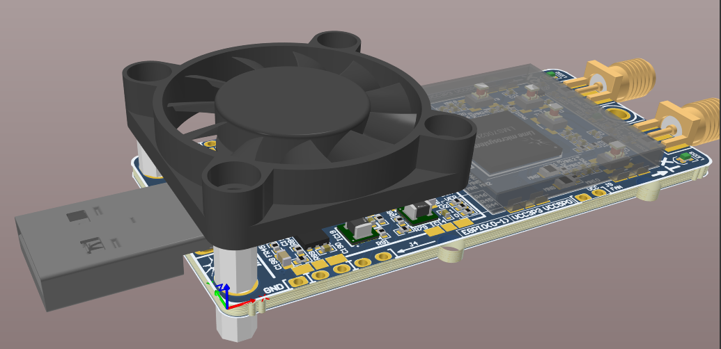
Figure 4: LimeSDR Mini v2.x fan mounting
Warning
You have to be careful when using mounting holes not to damage R72 resistor and C186 capacitor while there is no much clearence as you may see in Figure 5.
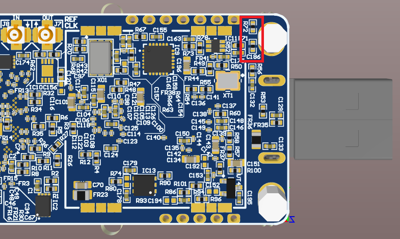
Figure 5: LimeSDR Mini v2.x mounting hole clearence
Recommended fan mounting solution is shown in Figure 6.
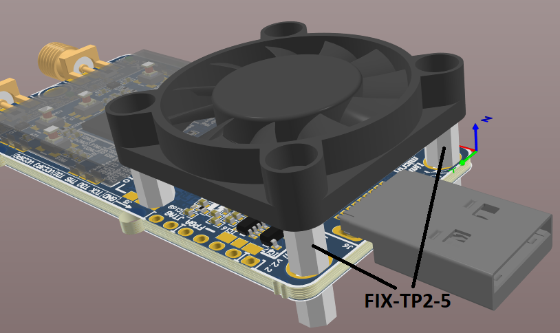
Figure 6: FIX-TP2-5 fan mounting components
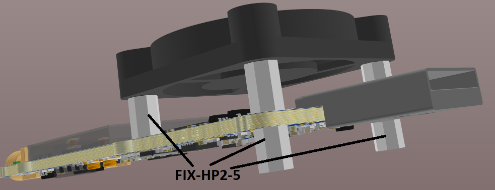
Figure 7: FIX-HP2-5 fan mounting components
Use two FIX-TP2-5 stands with internal and external thread (4mm width, M2 thread) as a spacers to mount the fan on top of LimeSDR Mini v2.x. Put FIX-TP2-5 stands from the top through LimeSDR Mini v2.x slot mounting holes around USB connector as shown in Figure 6. Secure the stands to the fan using two M2 thread screws (ex. P/N 1219480, Phillips head screw, M2x10). Secure two FIX-TP2-5 stands using two FIX-HP2-5 spacers as nuts from the bottom of the PCB as shown in Figure 7. This is enough to hold the fan but one may use additional FIX-HP2-5 (4mm width, M2 thread) stand with internal thread as an additional fan rest point which rests on PCB over unmounted J3 connector as shown in Figures 6 and 7. Secure FIX-HP2-5 spacer to the fan using the same screw (P/N 1219480).
Total required mechanical components per LimeSDR Mini v2.x:
2x FIX-TP2-5 stands with internal and external M2 thread;
3x FIX-HP2-5 stands with internal M2 threads;
3x 1219480 screws; M2x10 10mm length;
1x 4127/MF30060V1-1000U-A99 30mm fan.
RF Connections
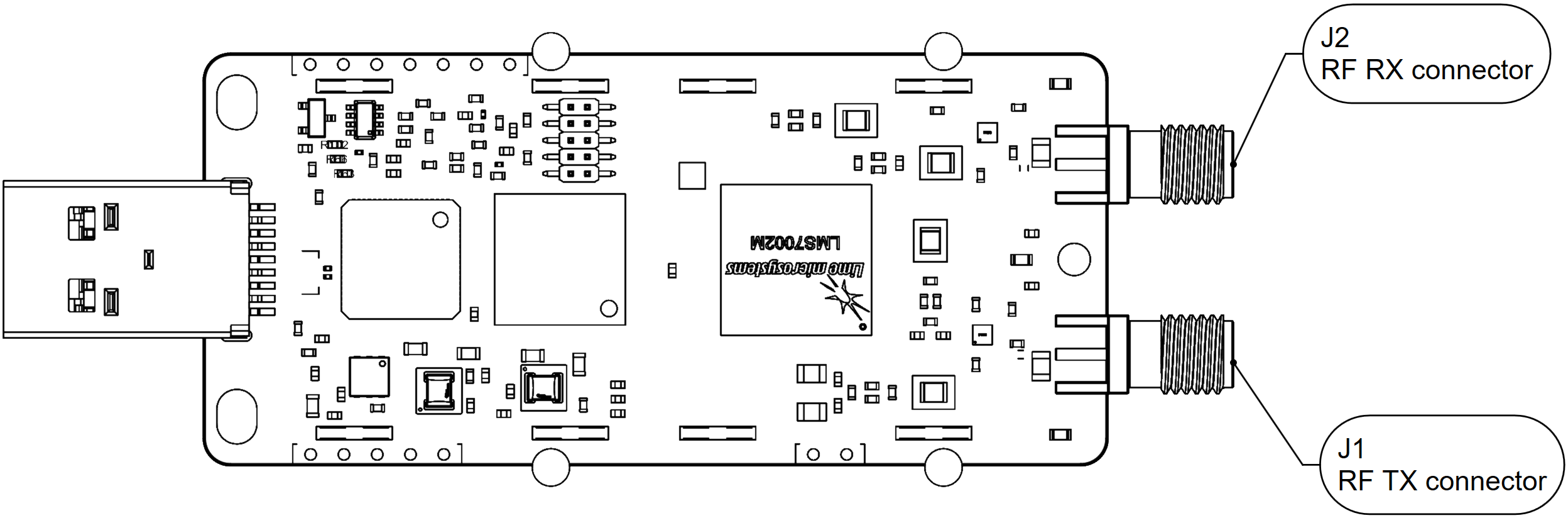
Figure 8: LimeSDR Mini v2.x board top with RF connector positions
Connector ID |
Connector type |
RF band |
Frequency range |
Note |
|---|---|---|---|---|
J1 |
SMA |
TX low |
30 MHz - 1.9 GHz |
transmit low frequency range |
TX high |
2 GHz - 2.6 GHz |
transmit high frequency range |
||
J2 |
SMA |
RX wide |
700 MHz - 900 MHz |
receive wide frequency range |
RX high |
2 GHz - 2.6 GHz |
receive high frequency range |
Warning
Care should be taken when connecting external RF signals to the RX inputs, to ensure that the maximum safe input power of +10 dBm is not exceeded, as this may cause permanent damage to the device.