LEDs
LimeSDR Mini board comes with three dual colour (red and green (RG)) indication LEDs. These LEDs are soldered on the top of the board near RF connectors.
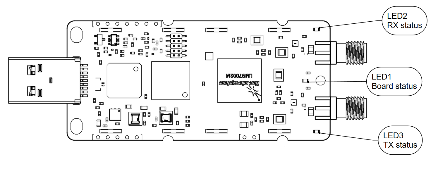
Figure 8. LimeSDR Mini v2.2 indication LEDs (top)
LEDs are connected to FPGA, hence their function may be programmed according to the user requirements. Default LED configuration and description are shown in Table 8.
Board reference |
Schematic name |
FPGA pin |
Comment |
|---|---|---|---|
LED1 |
FPGA_LED1_R |
V17 |
Board status: Blinking green = LMK_CLK clock is running; Red = USB control port is active. |
FPGA_LED1_G |
R16 |
||
LED2 |
FPGA_LED2_R |
R18 (FPGA_GPIO5) |
RX status: Green = DIQ data receive enabled; Off = DIQ data receive disabled. Shared with FPGA_GPIO4 and FPGA_GPIO5. |
FPGA_LED2_G |
M18 (FPGA_GPIO4) |
||
LED3 |
FPGA_LED3_R |
R17 (FPGA_GPIO7) |
TX status: Red = transmitting DIQ data; Off = no activity. Shared with FPGA_GPIO6 and FPGA_GPIO7. |
FPGA_LED3_G |
T17 (FPGA_GPIO6) |