RF Network Control
LimeSDR Mini RF network contains matching networks, RF switches, loopback variable attenuator and two SMA connectors (J1 - TX and J2 - RX) as shown in Figure 6.
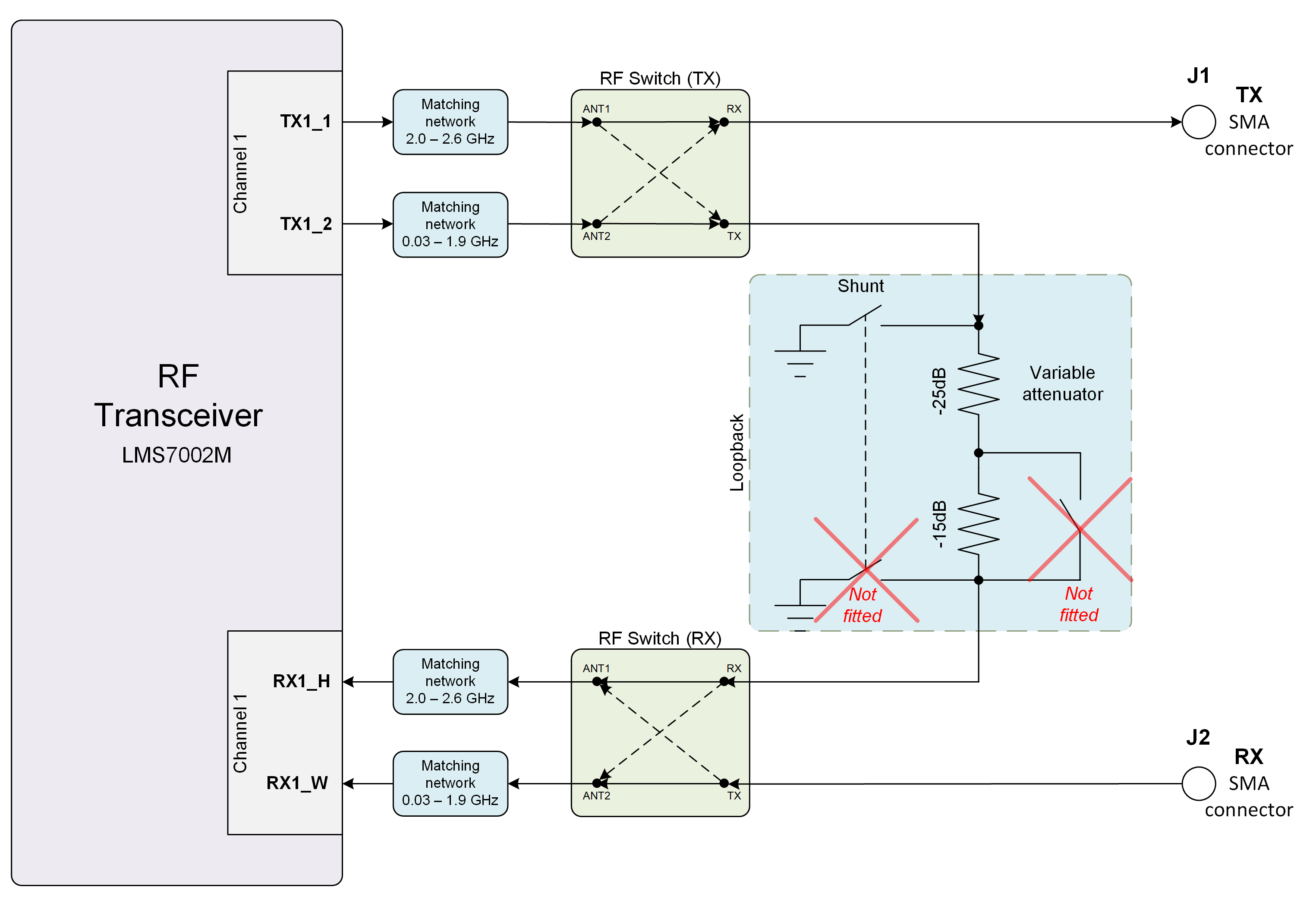
Figure 6. LimeSDR Mini v2.3 RF diagram
LMS7002M RF transceiver TX and RX ports has dedicated matching network which determines the working frequency range. More detailed information on LMS7002M RF transceiver ports and matching network frequency ranges is listed in the Table 3.
RF transceiver port |
Frequency range |
|---|---|
TX1_1 |
2 GHz - 2.6 GHz |
TX1_2 |
30 MHz - 1.9 GHz |
RX1_H |
2 GHz - 2.6 GHz |
RX1_W |
700 MHz - 900 MHz |
RF path control signals are described in the Table 4.
Component |
Schematic signal name |
I/O standard |
FPGA pin |
Description |
|---|---|---|---|---|
RFSW_TX (SKY13411-374LF – IC3) |
RFSW_TX_V1 |
3.3V |
B10 |
V1 – high V2- low TX1_1 to TX and TX1_2 to ATT, V1 – low V2 – high TX1_1 to ATT and TX1_2 to TX |
RFSW_TX_V2 |
3.3V |
C9 |
||
RFSW_RX (SKY13411-374LF – IC3) |
RFSW_RX_V1 |
3.3V |
C11 |
V1 – high V2- low RX_H to RX and RX1_W to ATT, V1 – low V2 – high RX1_H to ATT and RX1_W to RX |
RFSW_RX_V2 |
3.3V |
B11 |
||
Variable attenuator |
TX_LB_AT |
3.3V |
C8 |
High - -40dB, low - -25dB |
TX_LB_SH |
3.3V |
B8 |
Attenuator shunting. |